Introduction
I joined my lab in the summer of 2024. Resting in a case for some years was a $200k prototype for a mobile base with two 7‑DOF arms, made by Kinova (a company I’d later intern for). This “robot” was a collaboration between Stanley Robotics and Kinova: Stanley Robotics (later acquired by Locus Robotics in a series of purchases) developed the base; Kinova built the mobile manipulator with a neck on top.
Now, the problem with robotics companies is that they die all the time, and so do their documentation, code, and support. Sometimes, even ChatGPT never saw this thing because it doesn’t exist on the internet…
To the point: I became a private investigator, tracking people on LinkedIn at their current jobs to ask about a project they worked on 12 years ago. That’s a story for another time; I’ll share some desperate grad student stories later.
Opening the Box
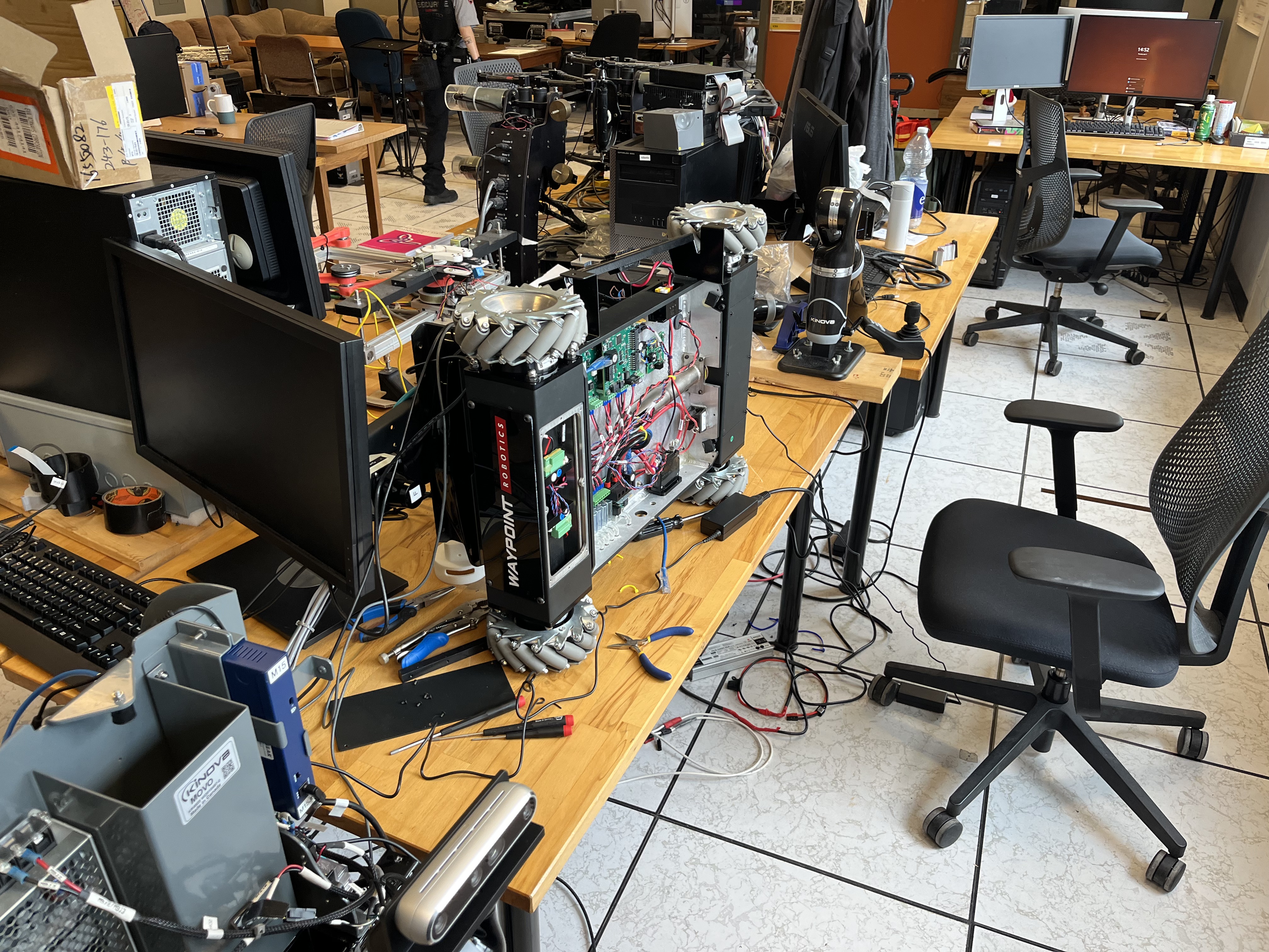
Without further ado, on my first day in the lab in June, I see a 1.5 m × 2 m black case with Kinova written on it. As I open it, I smell the dust of dust and think to myself: yeah, sh*t, I hope I don’t regret this.
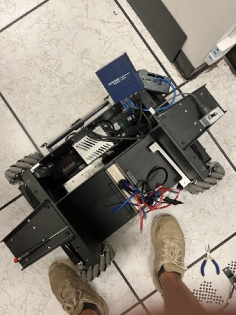
As we roll it down, I have no idea where to even start, so we put it to charge and, surprisingly, that didn’t work. We removed all the panels and stripped it down. You can even see the dust on the black panel.
Also, it arrived with one arm in the box, while the other had been used for research for some time, so I couldn’t find where the connectors nor mounts were, and nobody had any idea…
As I’m stripping it down, I’m trying to get to the batteries and the power distribution board to see what’s going on. After realizing this robot was not made to be opened (only to be assembled), it took real patience, Olivier, and God’s will to remove the case.
Now the real work begins.
Battery dead but alive
As you take this thing apart, you notice that the base is where everything runs from. It decides what turns on what and when.
It became clear that if we solved whatever issue the base had, the whole thing would “just” be a software issue…
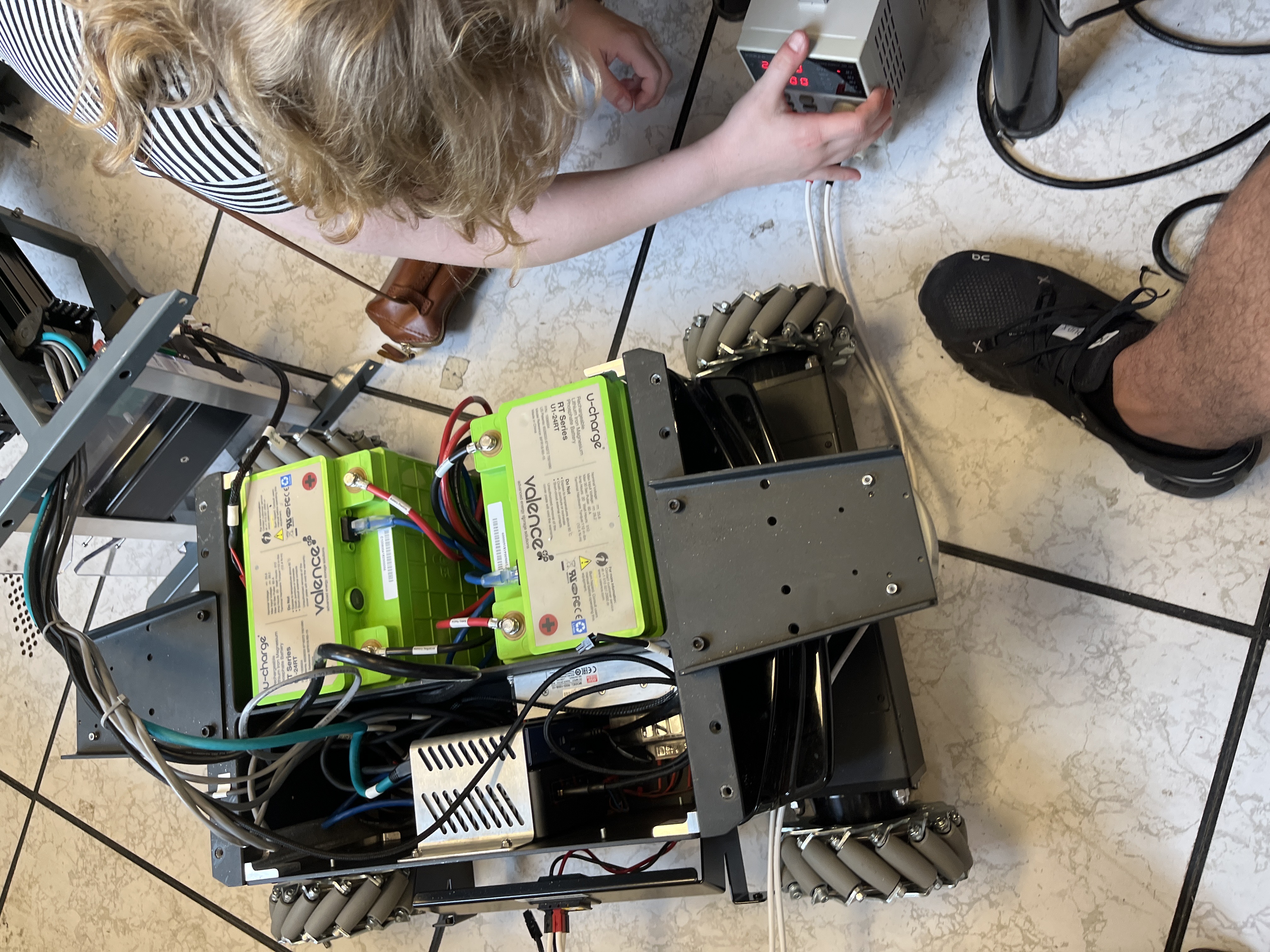
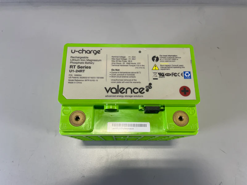
Until you open the thing and look closely and see a third cable coming out of the batteries. I remember paying attention in physics class and nobody told me batteries need 3 cables: a positive, a negative, and a goddamn ethernet‑looking cable. That’s when I realized the days of AliExpress parts, ESP32s, and Raspberry Pis were over, I’m doing real robotics now. So the next day I tried to get to the bottom of what was going on. More surgery and digging:
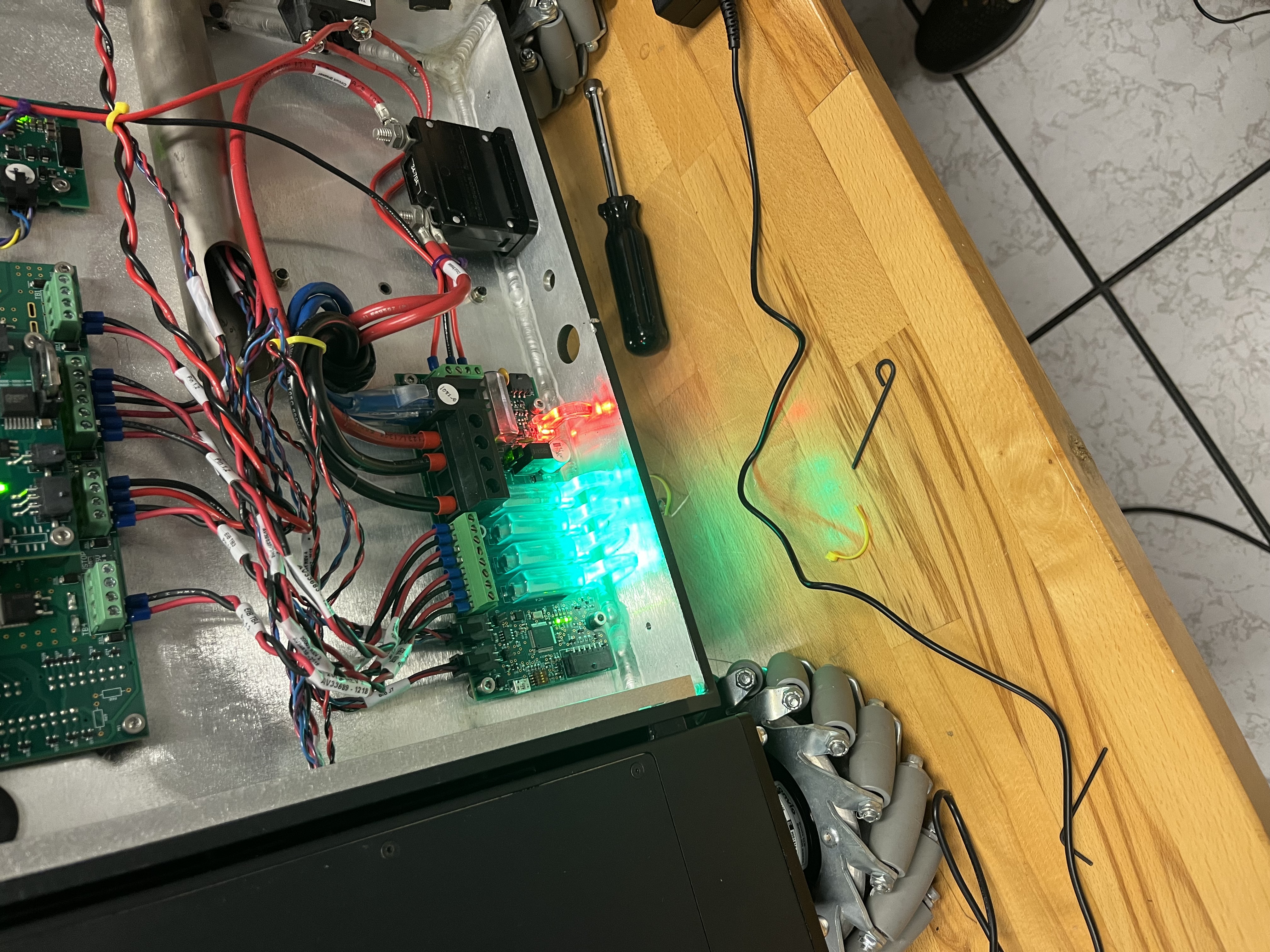
We get three boards, one with a chip and one that takes in a CAN signal. When powered on, the board flickers and then, after a minute, powers some little things and dies. People say “okay, the battery needs to charge…” Sure.
Either the thing will work or it won’t… working for exactly one minute then shutting down makes no sense. Turns out the embedded system expects an OK message from the batteries, and since the batteries were not in good condition, it would never send that signal, so the system shuts down for safety.
Now you might think: “okay, just buy new batteries, same ones, problem solved.”
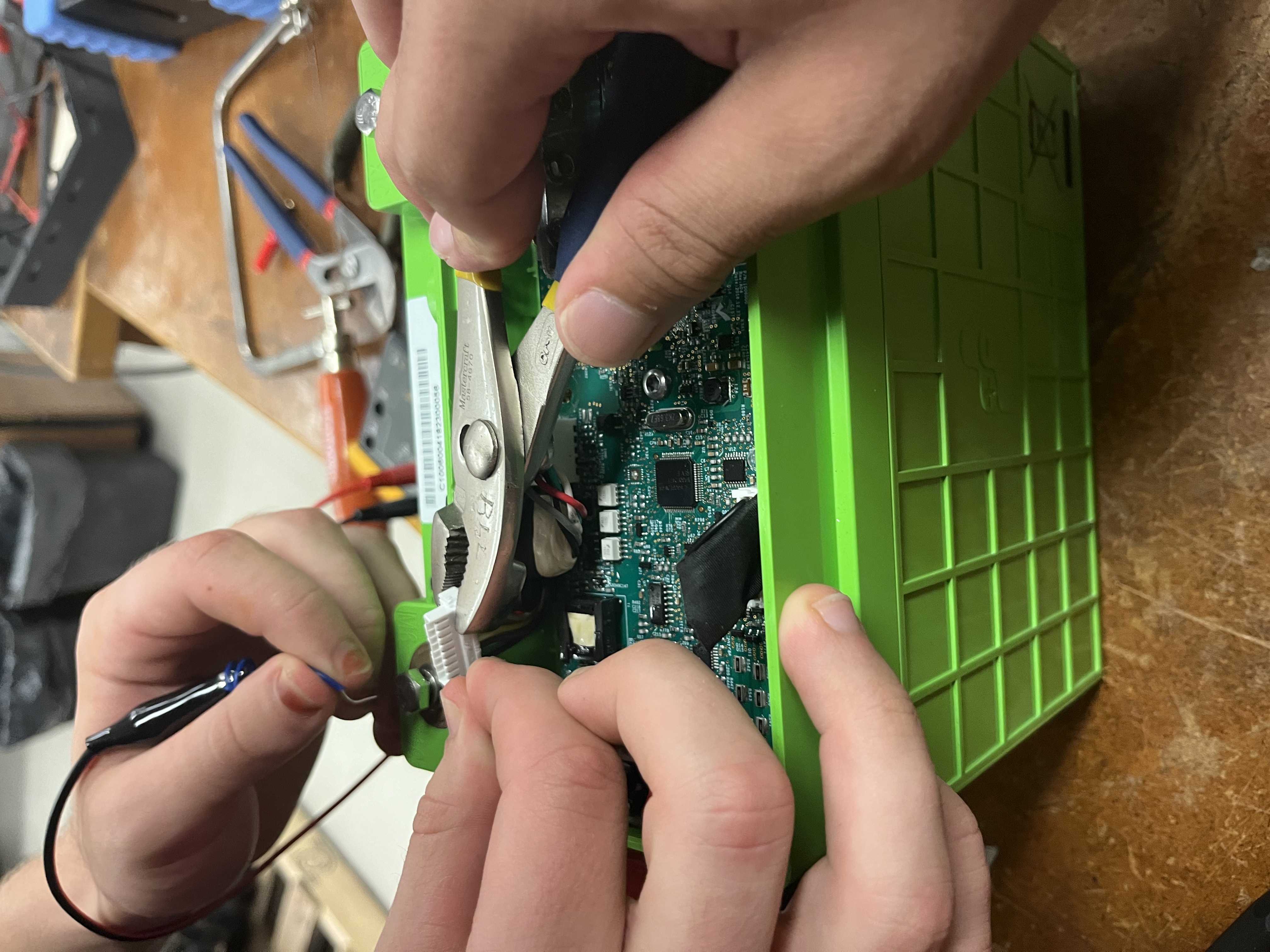
Well, you’d be wrong because the company that made them did it 10 years ago; they don’t make the same ones anymore, you don’t have access to the firmware on that chip, companies got acquired, and you’re left with no batteries and a dead $200k robot. The only hope is to rebuild everything yourself. However, we didn’t give up. We opened those batteries, trying to fake that signal.
Well, that didn’t work because there was zero documentation. Luckily, I found a second‑hand battery seller in the US who had similar packs with a bit lower voltage but still workable, so we bought those and used them.
The problem was still going on; it didn’t want to boot, until one day, something lucky happened and it armed the arms and all motors. But this phenomenon only happened once and we never saw it again.
New Solution
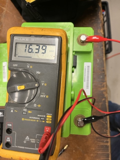
After years and years of sitting closed up, the batteries were dead, although they were “smart” with a BMS you can connect to via a kind of “CAN‑bus” cable. You could read voltage, but you could not (re)enable what mattered.
When powering this thing, it goes through a 1‑minute boot… and because the batteries are “dead,” there is no way it allows those embedded boards to power the entire system. We opened the batteries, tried to charge them slowly, tried to trick the BMS,and when weird smells start showing up, that’s when you know you need a different direction. We even got the “same” batteries, but because of the lack of documentation and troubleshooting, we changed course. Two months lost.
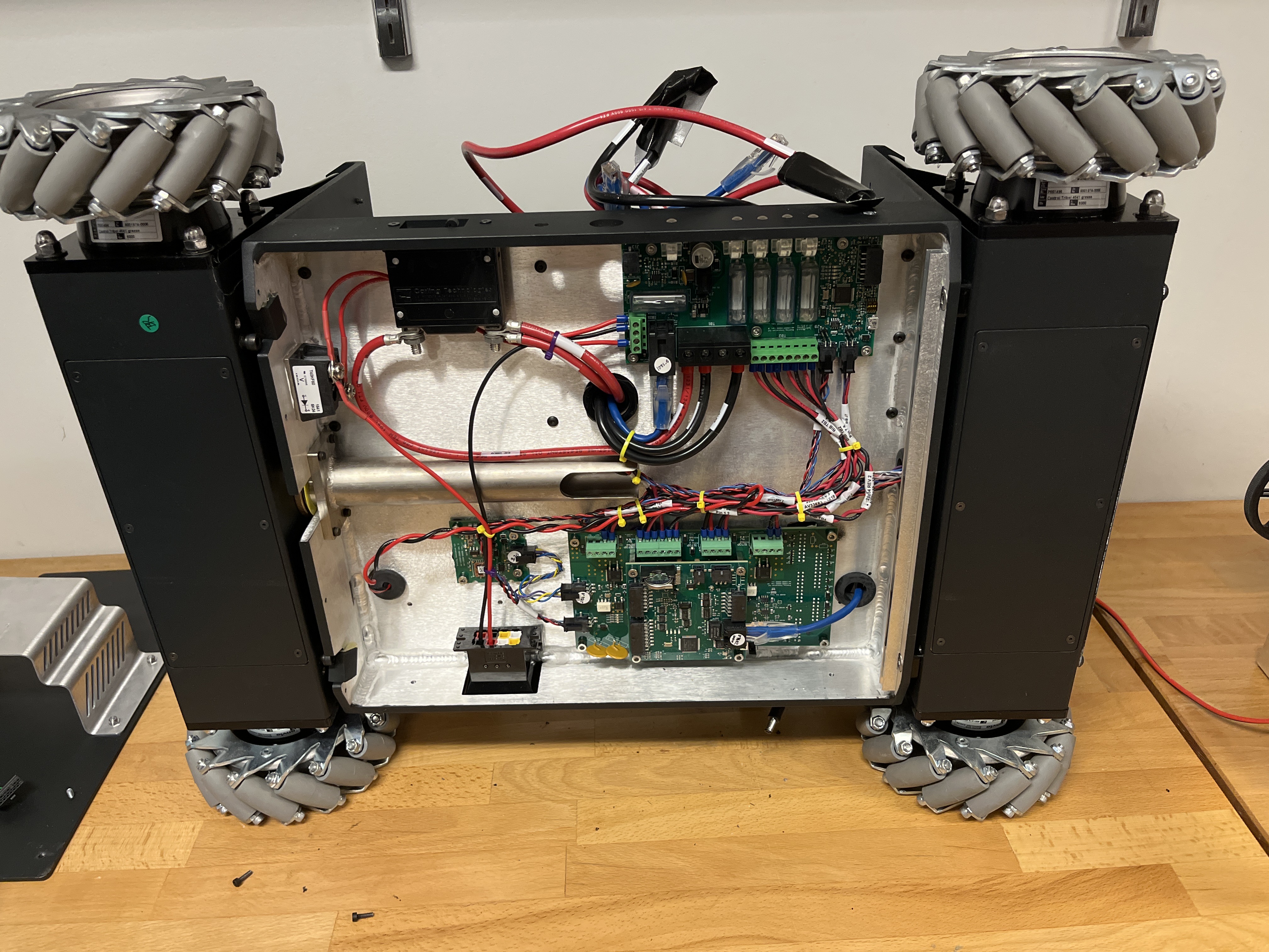
The base stack consisted of 4 Nanotec motors, 2 batteries from an unverified manufacturer, and a collection of boards with no documentation. Needless to say, the robot was a nightmare. After trying every single possible solution, it became apparent I needed to start from scratch. The biggest issue is the base, everything in the start‑up cycle is there: Power → Batteries → Motors + Sensors. So step one: how do we solve the battery issue? Throw every single board out and start from first principles.
Base Moving
The base was solid: 4 omni‑directional wheels with high load and good motors. The problem was interfacing.
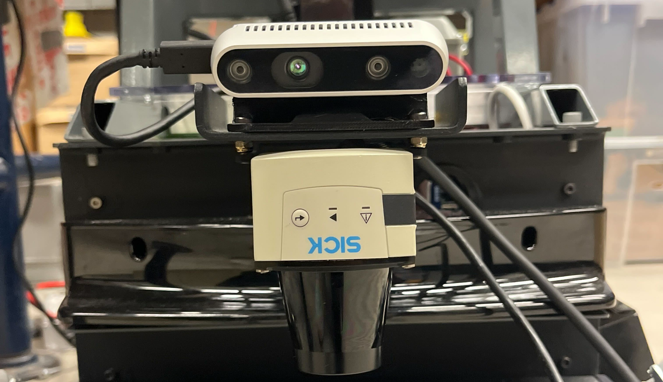
Sensors included an IMU and two SICK 2D LiDARs, cool in 1994 but they very good build. We added two RealSense cameras (front and back) and a 9‑axis IMU, and brought up a ROS2 interface we’d need later.
The most important goal was to move the motors. I started with one. These motors had a whole interface and so on but pretty much no documentation. After digging and digging, I got code sending velocity to the motors. There are two ways to control velocity: either with a set acceleration ramp or with direct velocity (it will try to reach that velocity ASAP, not great).
After setting up the whole bus with the other motors, the code could send velocity commands by ID. With omni wheels, you essentially command x, y, and angular z. Setting that up was tricky, especially during sudden direction changes, some motors would go faster than others and take time to catch up.
When you’re doing projects like these as a grad student, you don’t have time to set up a perfect testing environment. The number one goal is to get things done, one way or another.
Integrating ROS2 in the Base w/ NavStack + Sensors Setup
We fused the IMU and depth, got a clean ROS2 bring‑up, and slotted in Nav2. Nothing flashy, just stable, debuggable foundations so the rest of the stack wouldn’t crumble.
New Neck
The MOVO came with an Xbox Kinect on a 2‑DOF neck. The neck was deeply integrated into the embedded system of the base (worst design decision I’ve ever seen).
I tried to reverse‑engineer the neck control; it was a learning experience (meaning it didn’t work). So I asked my mechanical engineer friend Umer Nawaz to help: we built a new neck with two servo motors and reused the original mounting space.
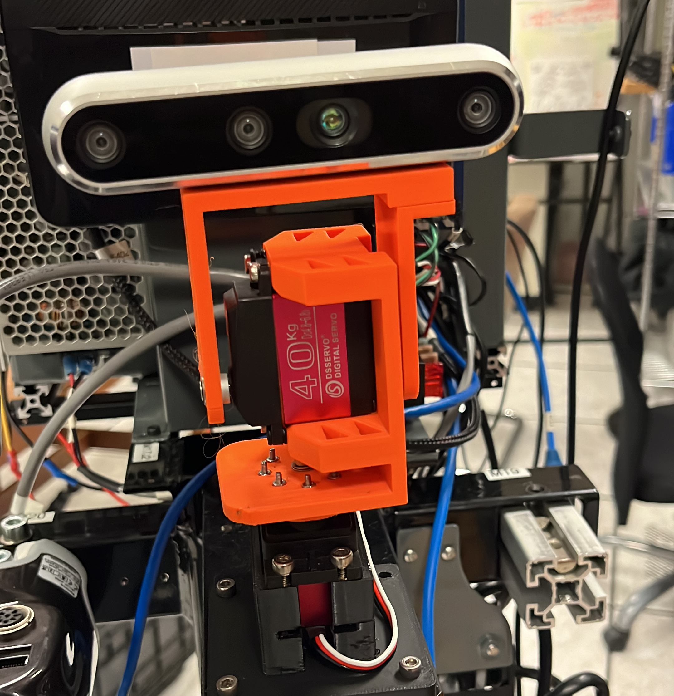 Since it’s not 2009 anymore, I swapped to a RealSense on the neck.
New Mounts
Obviously, nobody cares about a base that just moves around, interaction is the point.
We’ve got two Jaco arms: one working, one broken, and extremely complicated mounts. I’ll go in depth later (it’s also my research).
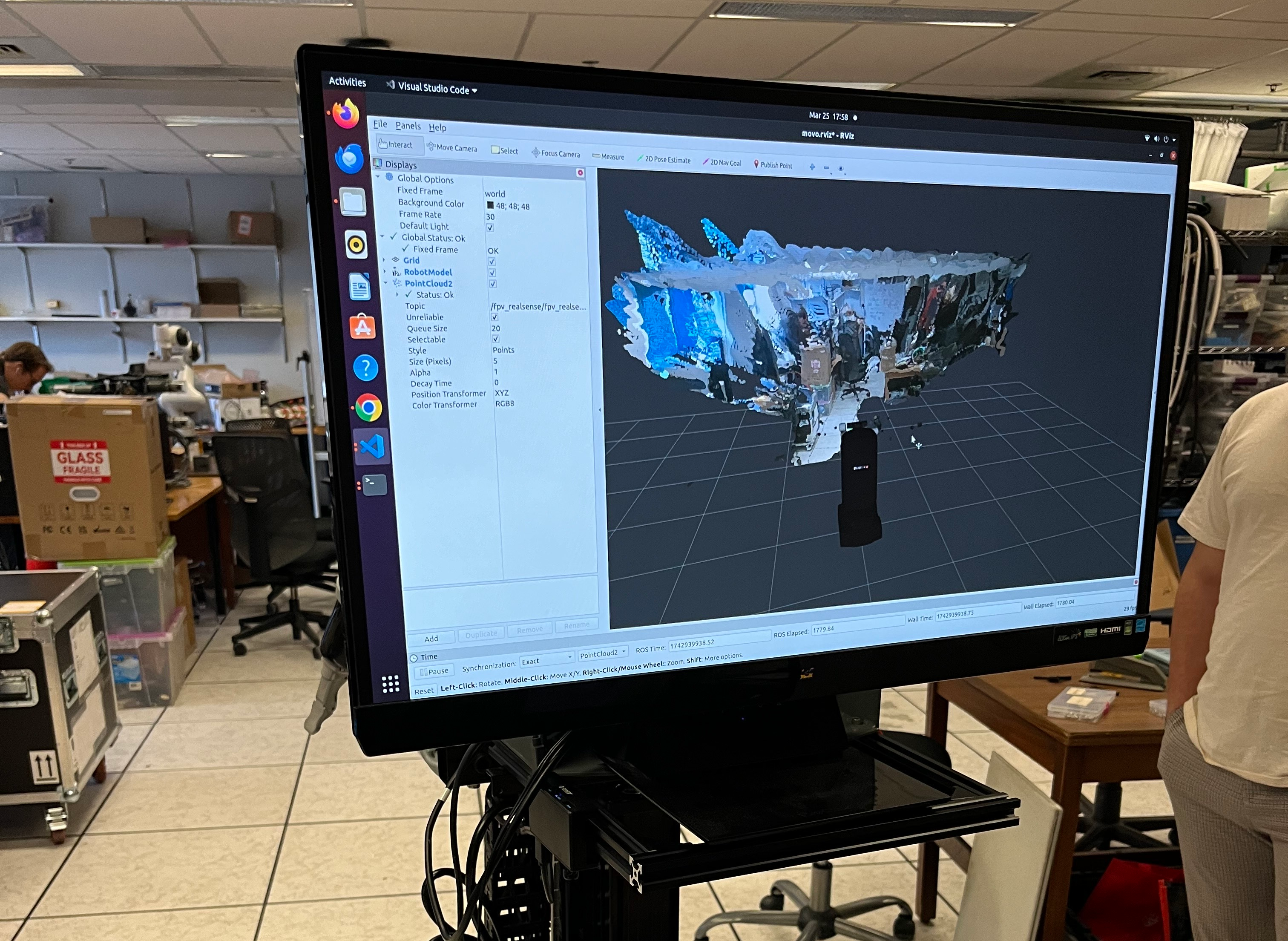
My first step was learning the Jaco on its own. I set up a station, plugged it in, and started playing. I knew a bit of ROS but nothing like this. Publishing to a real arm that costs a couple of thousands is nerve‑wracking, but you get used to it. First step done: RViz + RealSense to see the environment,very cool.
Next, figuring out how the arm worked with the MOVO. Normally, the control computer resides at the base of the arm, but for MOVO they made a custom encasing, moved it outside, and changed the base with a custom mount that plugged straight into the MOVO.
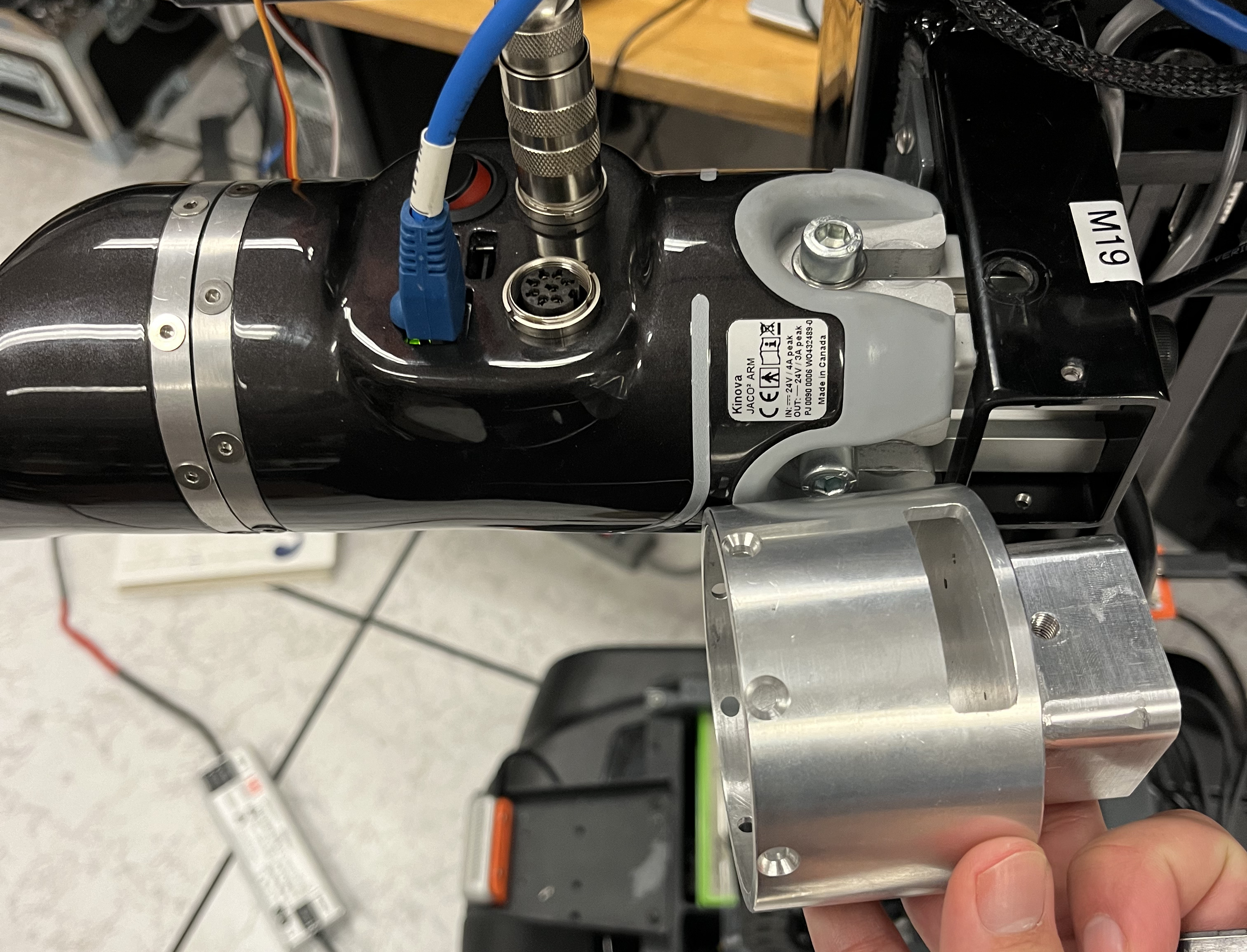 Problems: hardcoded addresses, control hardware locked and couldn’t be updated, flex cable + loose wires, and a missing shoulder mount. I reverse‑engineered the part, sent it to McGill machining, and it worked like a charm.
Those computers still had issues and wouldn’t work on my system. So I got rid of those mounts, brought back the original bases, and made a custom 4040 extrusion setup. Now the arms could be updated, connections solid, and the mounting better. Simpler really was better.
Dual‑Arm Bringup & Ops
The Kinova SDK and ROS package did not support dual‑arm manipulation over Ethernet. So I made my hands dirty. I changed some code and, after a couple of hours, had a whole package, movo_bringup, working seamlessly. Dual‑arm manipulation with a config file for all the specific arm parameters; everything worked together.
 Then I got a message: the CEO of Kinova would visit the lab. Time to rush dev plans. Next steps:
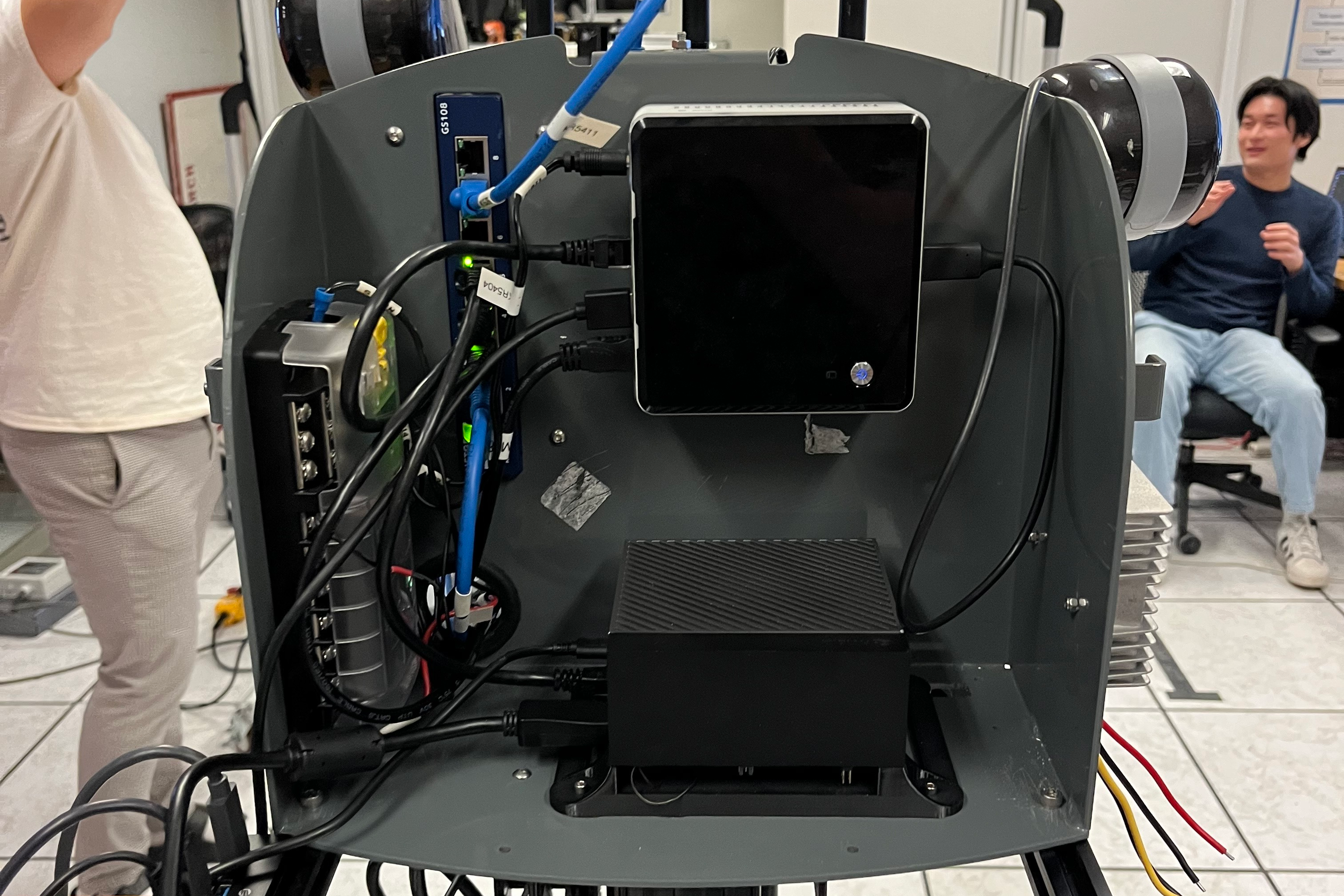
- Screen for data collection/status.
- Jetson Orin for on‑board AI.
- Router so a separate computer can watch via ROS2.
We made a custom mount for the Jetson. With some router mounts, the whole thing worked perfectly. Through ROS1 you could just connect to that Wi‑Fi, set your computer on the same network, and rostopic list would work, ROS2 setup is different, but we made it smooth.
PS. The Charles Deguire (CEO of Kinova) loved it so much, I ended up getting an Internship at Kinova.
A robot for AI…
There is a lot I did not want to cover here, I can write a whole thesis about this Robot, I spent 6 Months on it, I loved every second of it, part of me saw it as a challenge but another part of me saw it as a rite of passage to my journey as a roboticist. I would do it all over again.
Up to now you might see this as an “engineering project” rather than research. Where’s the research? What’s the point of spending all this time making it work? Other than loving this stuff, the point was doing research with bimanual mobile robots. So here’s the goal: build the AI infrastructure to collect, train, and deploy on the MOVO.
I will talk about this in another blog.