Introduction
Let’s be real: simulations are amazing, until you remember that robots are actually made to exist (and do stuff!) in the real world. When I first started getting into robotics, everyone kept saying two things:
- “ROS sucks!” (and the more optimistic ones add, “But it’s the best we’ve got…”)
- “Try it in a simulator.”
Simulations can be fantastic for early testing and debugging. They’re reproducible, they’re (relatively) cheap, and you don’t have to worry about your robot destroying itself. But here’s a fact you can’t escape: real robots, real hardware, real environment. That’s the only thing that truly matters once you move beyond code into the physical world.
As the old saying that I just made up right now goes: it’s way cooler to see a real robotic arm peel an orange than to watch it “cook, drive a plane, and play chess” in a simulator.
With that in mind, I decided to build a fully functional robot arm environment—something safe, solid, and ready for my experiments. In this blog post, I’m going to share the entire process: from design to assembly to getting everything powered and ready for some sweet, sweet data collection.
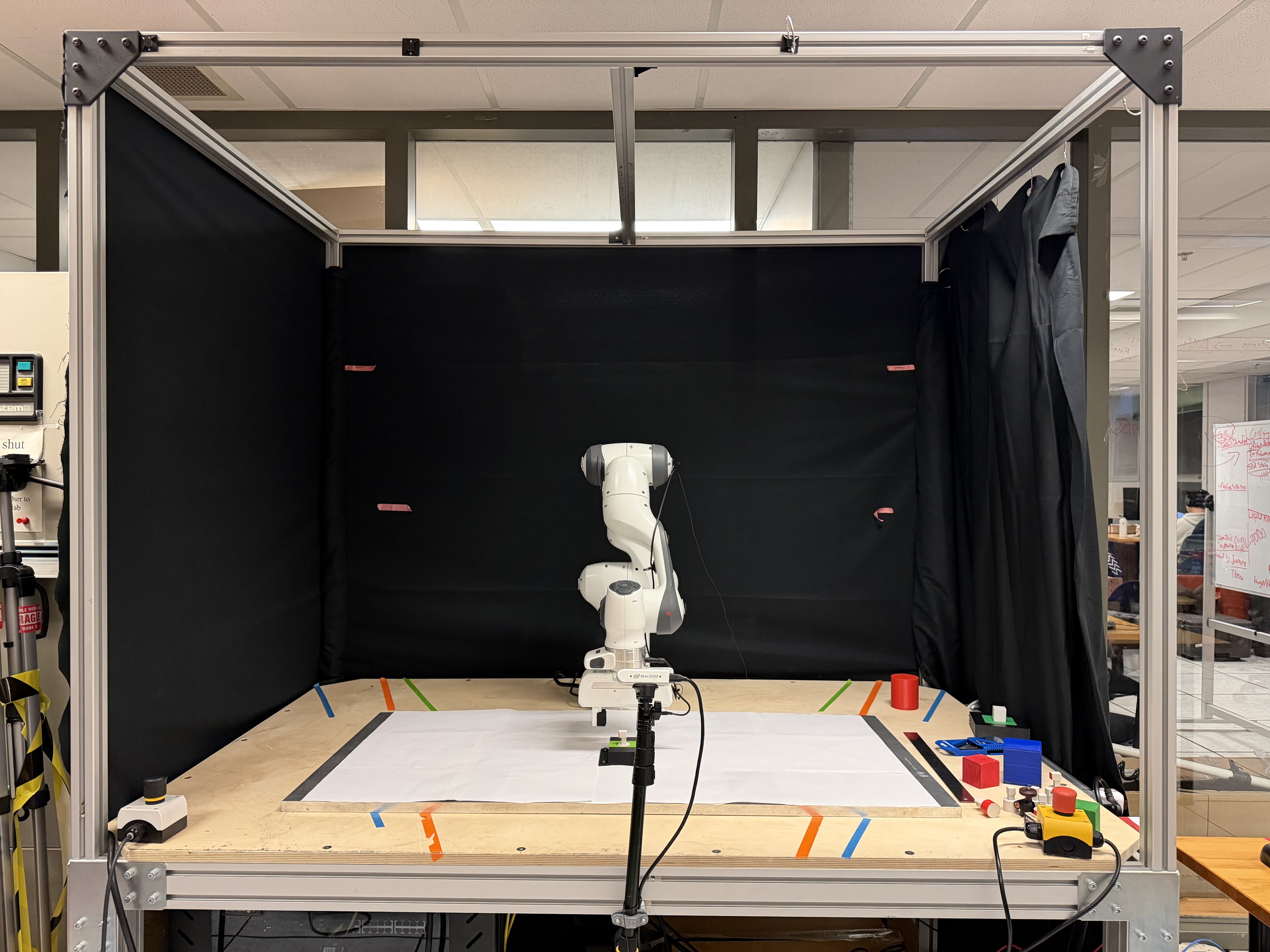
This is what the final project ended up looking like.
Why a Real Robot Environment?
You might be asking: “Why build a custom table/cage setup in the first place?” Well, simple: my old environment was terrible. (Yes, I needed a table because my previous setup was… let’s just say “suboptimal.”)
- Stability: Throwing a heavy robotic arm onto a flimsy table is basically a recipe for everything toppling over.
- Safety: Having a dedicated environment where you can bolt everything down, add kill switches, and properly manage cables is worth more than gold.
- Scalability: With a sturdy environment, you can keep adding sensors, extra arms, cameras, lights…
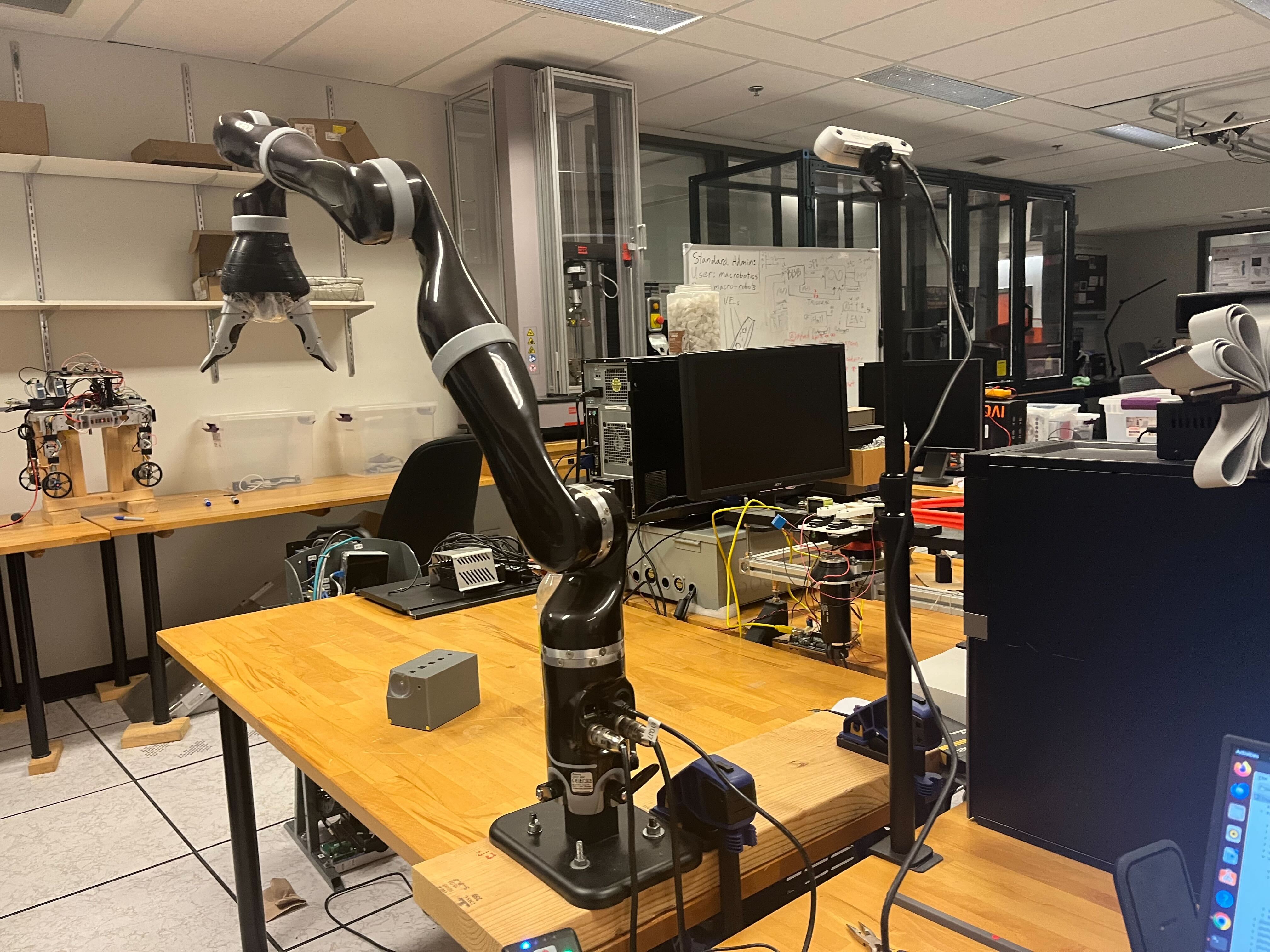
The initial setup was unstable and posed safety risks.
As you can see, my initial setup is very dangerous and it’s very annoying to set up every single time…
Step 1: The Design
Key Consideration: Cost
Money is a scarce resource, especially in research where everybody complains about it. I convinced my supervisor that the environment would cost around $1500, which might sound like a lot or a little, depending on your project scope. In reality, you can source most of the necessary materials (extrusions, brackets, plywood, cables) from places like Amazon, AliExpress, or local hardware stores.
Online Tools
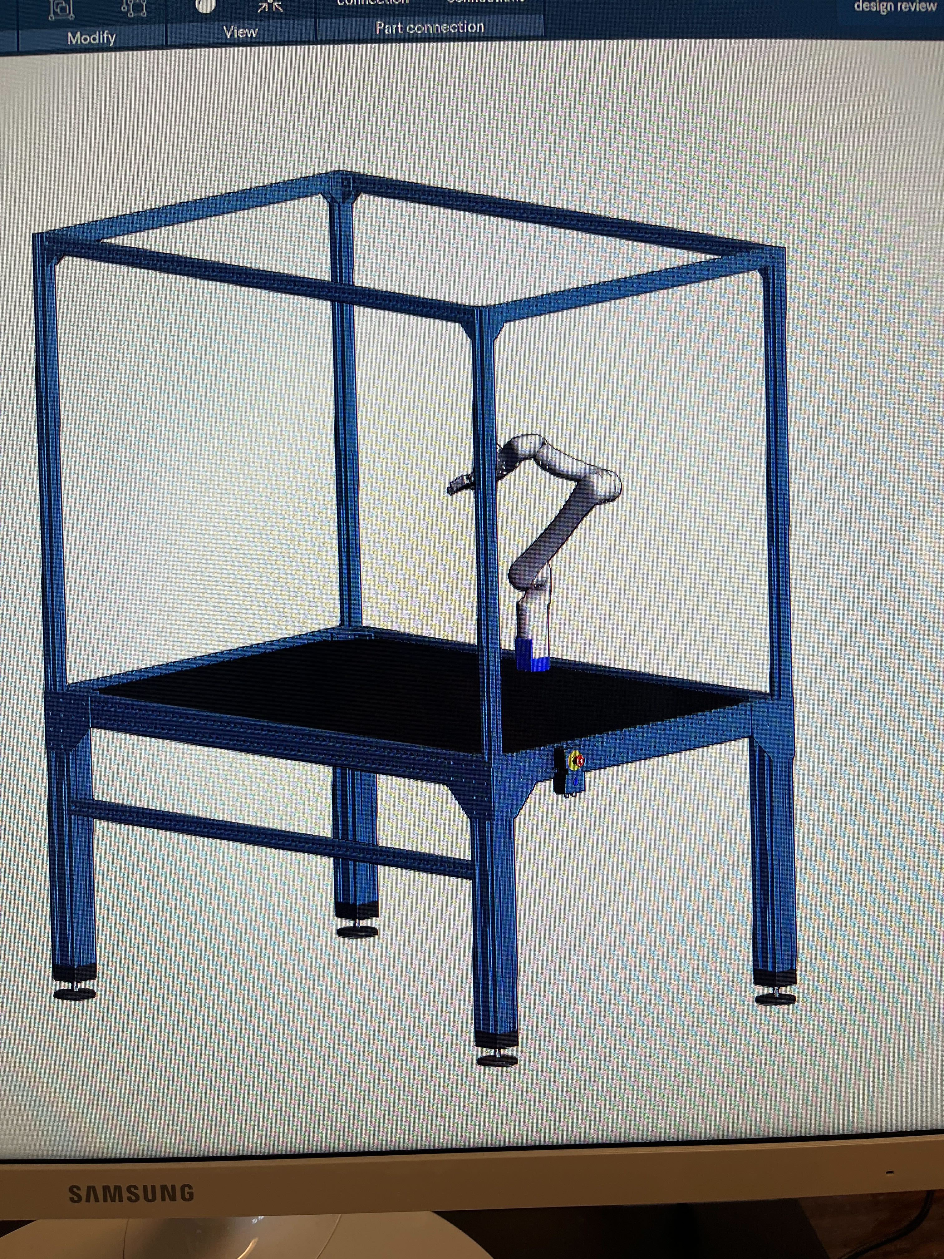
Using Vention’s online builder to design the frame.
Even though you can totally draft this on paper (it’s just a table, not a rocket), I used Vention’s online builder to visualize my idea. It’s like if Canva and Fusion 360 had a baby specialized in industrial setups. They have all sorts of aluminum extrusion models and accessories so you can plan how everything will fit together in 3D. But be warned: Vention itself can be pricey, so I used it mainly as a design tool, then sourced the actual parts elsewhere. It was 3× more expensive…
Step 2: Building the Frame
Choosing Aluminum Extrusions
I’ve worked with a bunch of different materials over the years, and aluminum extrusions are my go-to for making a robust frame. They’re light, strong, easy to work with, and they don’t rust. Plus, you can attach things to them without needing to drill a thousand holes.
Here’s what I used:
- Four 8080 extrusions (80 mm × 80 mm) for the table’s vertical legs (“feet”). These are thick, beefy columns. The “8080” basically means each side is 80 mm wide, forming a nice square cross-section.
- 8040 extrusions (80 mm × 40 mm) for the horizontal perimeter beams of the table. These create the top frame that holds the tabletop.
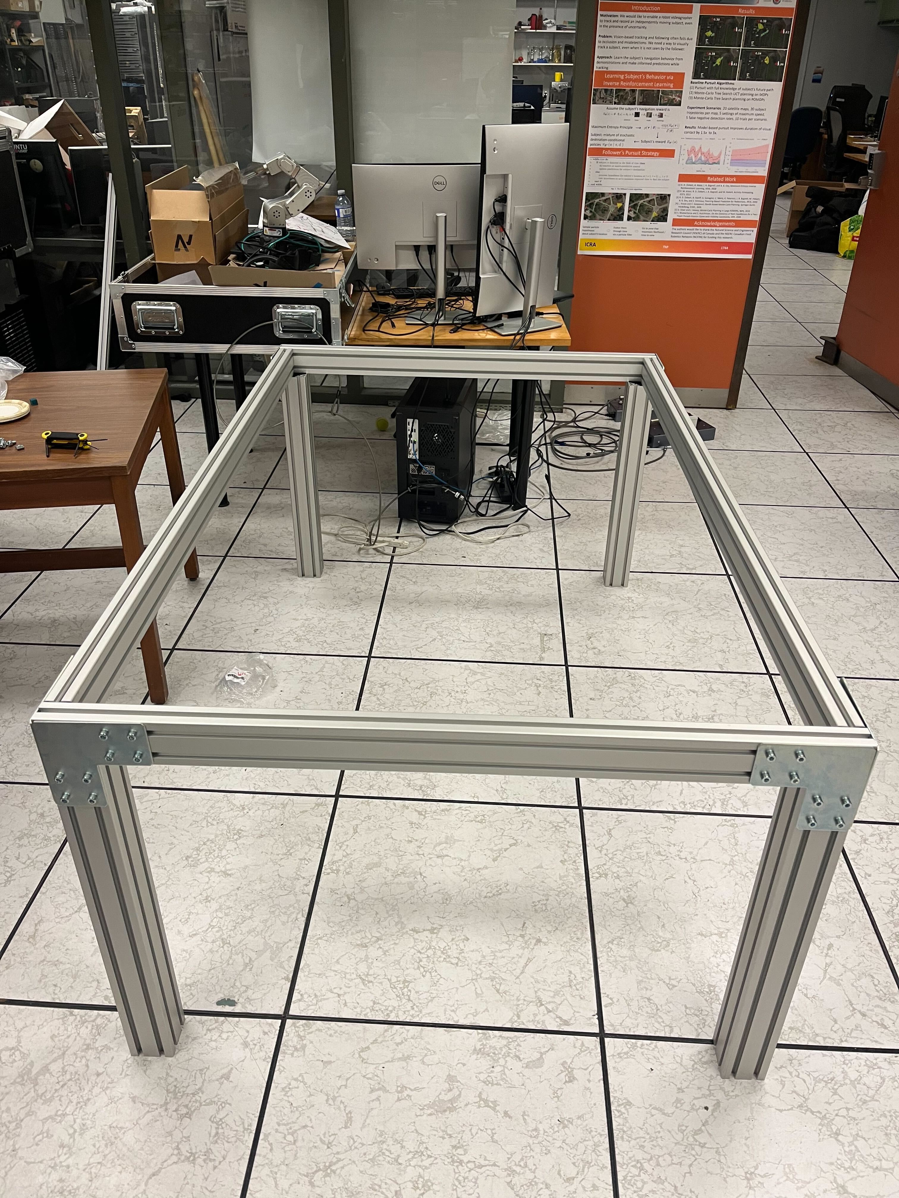
8080 and 8040 aluminum extrusions used for the frame.
I chose 8080 for the legs because they can handle a lot of weight and vibration without wobbling. For attachments, I used T-slot nuts with ball bearings so that the connection stays snug and won’t shuffle around under stress. Then I used corner brackets wherever needed to ensure the frame remained rigid. I also had two 4040 pillars go through the middle so that it limits the tabletop wobbling.
Height & Dimensions
A good robot worktable is typically around 30 inches (76 cm) tall—or a bit taller if that’s more ergonomic for your use case. My table is somewhere around 80 cm, which works nicely for me. Measure your lab or workspace carefully.
Step 3: Adding the Cage
I wanted a sort of “cage” or overhead structure on top of my table to mount:
- Lights
- Cameras
- Extra sensors
- Anything else that might need overhead rigging
Because the cage doesn’t bear much weight or stress, I used 4040 extrusions. It’s basically a rectangular structure extending above the table, with vertical posts at the corners and crossbeams on top. This allows you to attach cameras in all sorts of angles.
Tabletop Installation
For the tabletop, I grabbed a thick plywood sheet. Don’t skimp here; you want something that can handle repeated drilling, screwing, and the weight of your robot without warping. I had my university’s workshop cut it to the exact dimensions I needed.
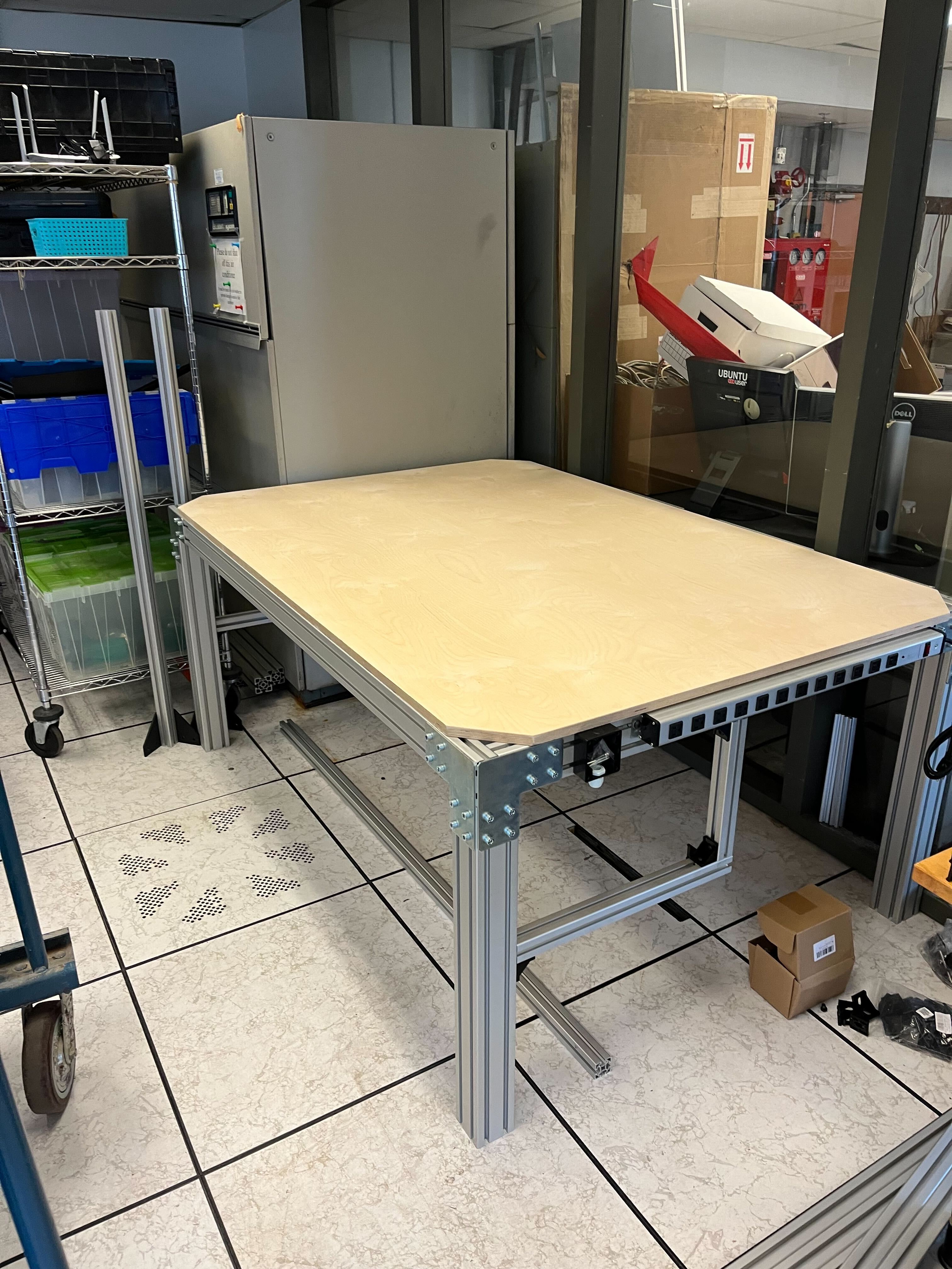
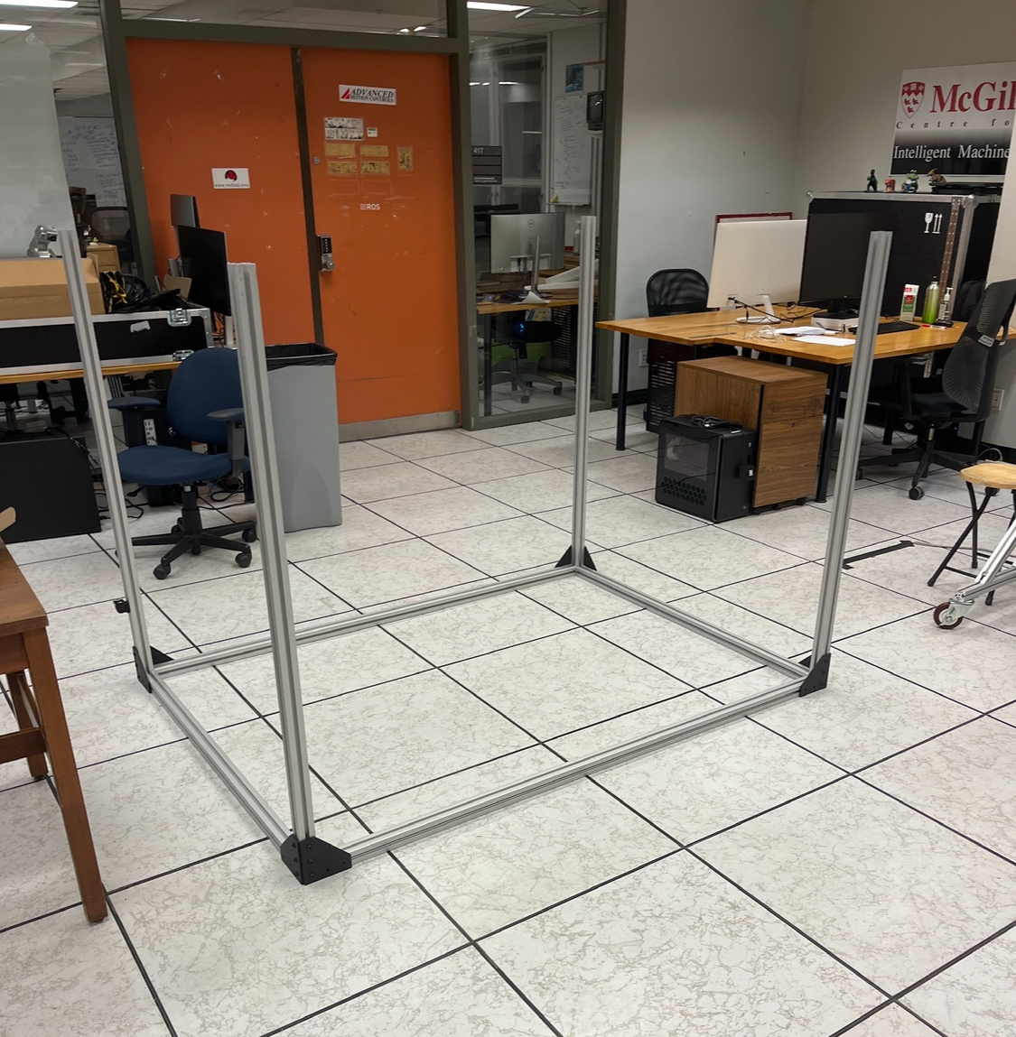
Tabletop assembled and the table cage.
Pro Tip: Cut off the corners of the tabletop if your cage legs attach right at the table’s corners. That way, the aluminum posts can align flush with the frame.
Flush Screws
I used a step drill bit to create funnel-shaped holes in the plywood, allowing the screw heads to sit flush with the surface. Looks neat, and the robot’s base can sit directly on top without rocking on a protruding screw.
Step 4: Power Management and Safety
Power Strip & Cables
I attached a 12-outlet power strip along one side of the table. This is a total lifesaver. Robotics experiments inevitably lead to connecting lots of devices like arms, sensors, lights, single-board computers, you name it. Having a big, well-secured power strip means everything is accessible and you’re not tripping over extension cords.
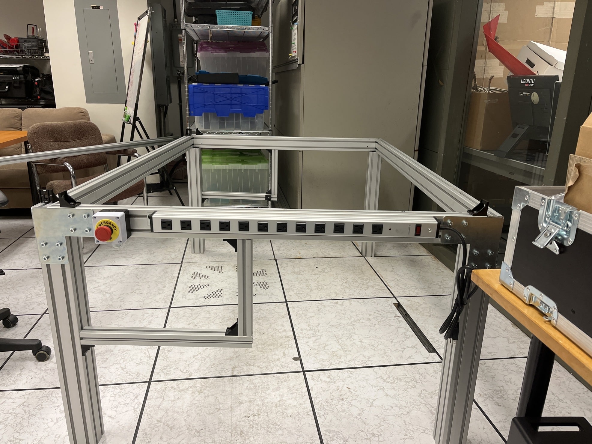
Kill switch and power extension.
The All-Important Kill Switch
No self-respecting robotics setup should be without an emergency kill switch. If (when) your robot decides it’s time to rebel (or most likely your code is made by ChatGPT), you want a giant red button that kills power to the robots instantly. I mounted mine on the side of the frame.
Step 5: Mounting Sensors and Setting Up Lighting
Cameras
For depth perception and all the fancy stuff, I use Intel RealSense cameras:
- One is clamped in front on a little monopod (attached to the table edge).
- The other is mounted on the overhead cage via a custom 3D-printed bracket.
These positions help me capture different angles and feed data back into my system for object detection, tracking, and all that good vision-based robotics stuff.
Lights
You need good lighting if you’re doing any kind of computer vision. I picked up some affordable USB-powered LED lights from Amazon. These attach to the overhead extrusions. They’re bright enough to illuminate my workspace without blowing out the camera exposure.
Step 6: Bringing in the Robots
Finally, the fun (and sometimes terrifying) part: the robot arms. We had two Kinova Jaco arms, which are wonderful (but old) because:
- Controlled via Ethernet (plugged into my switch).
- They’re relatively safe, with configurable velocity limits (keep that kill switch in reach!).
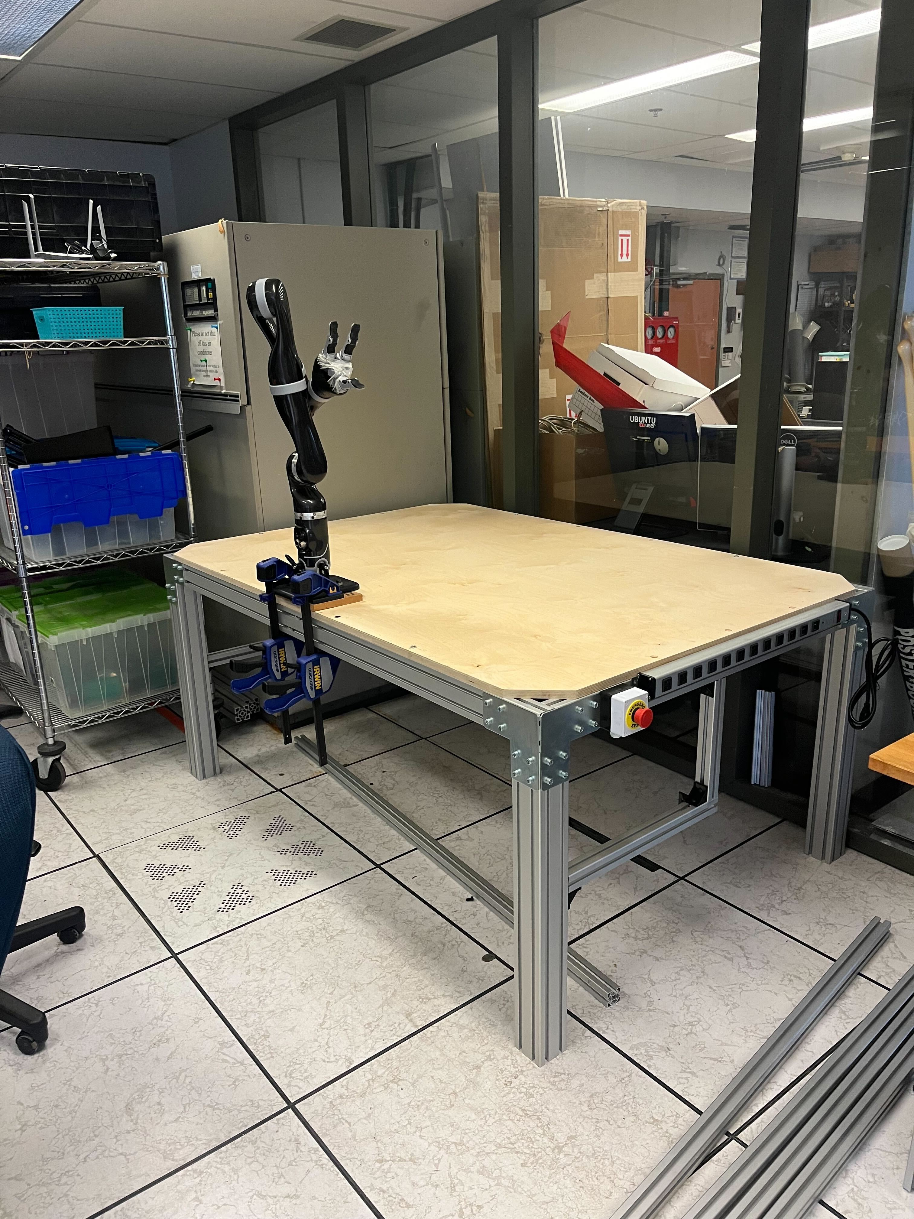
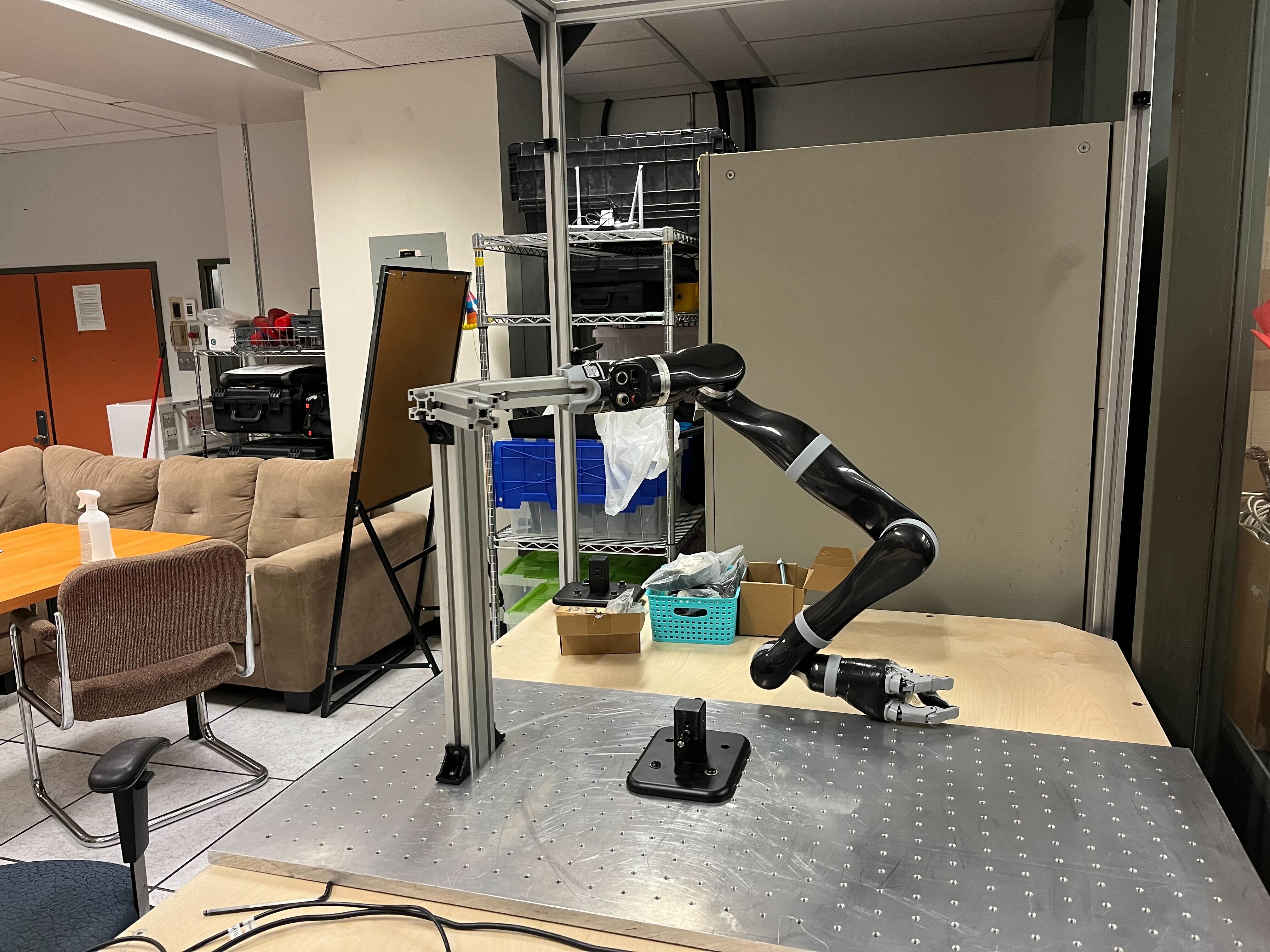
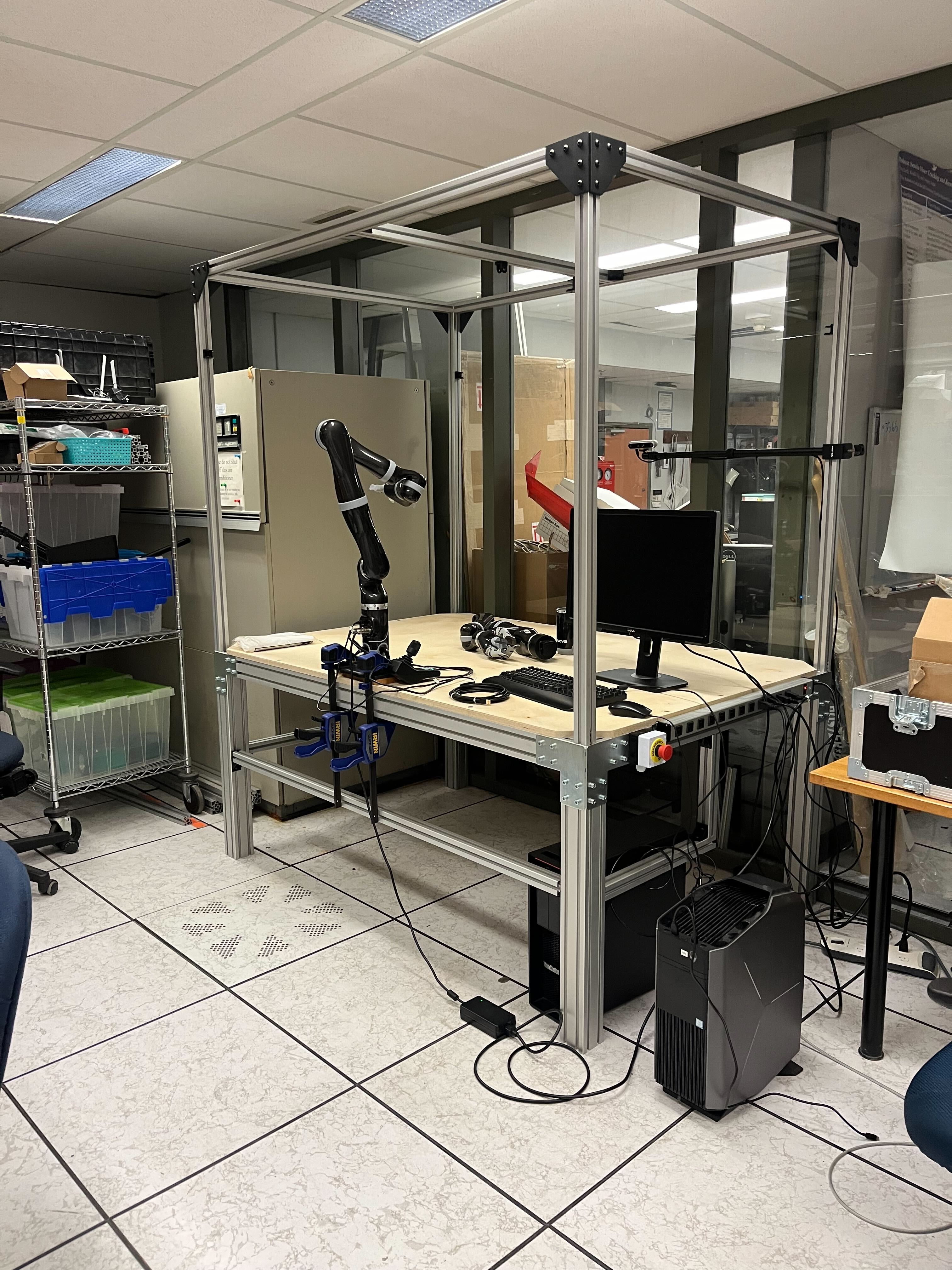
Kinova Jaco arms mounted securely with proper power distribution.
I placed them so that the base is firmly attached (later on I used an optical plate we had, which is a fancy word for an aluminum plate with M8 holes on it) onto the tabletop, with the cables running underneath to my power distribution unit. That distribution unit then feeds into the main power strip, all behind the kill switch.
Important: Make sure you secure the robot base very well. The last thing you want is your robot deciding it’d like to take a stroll across your lab bench.
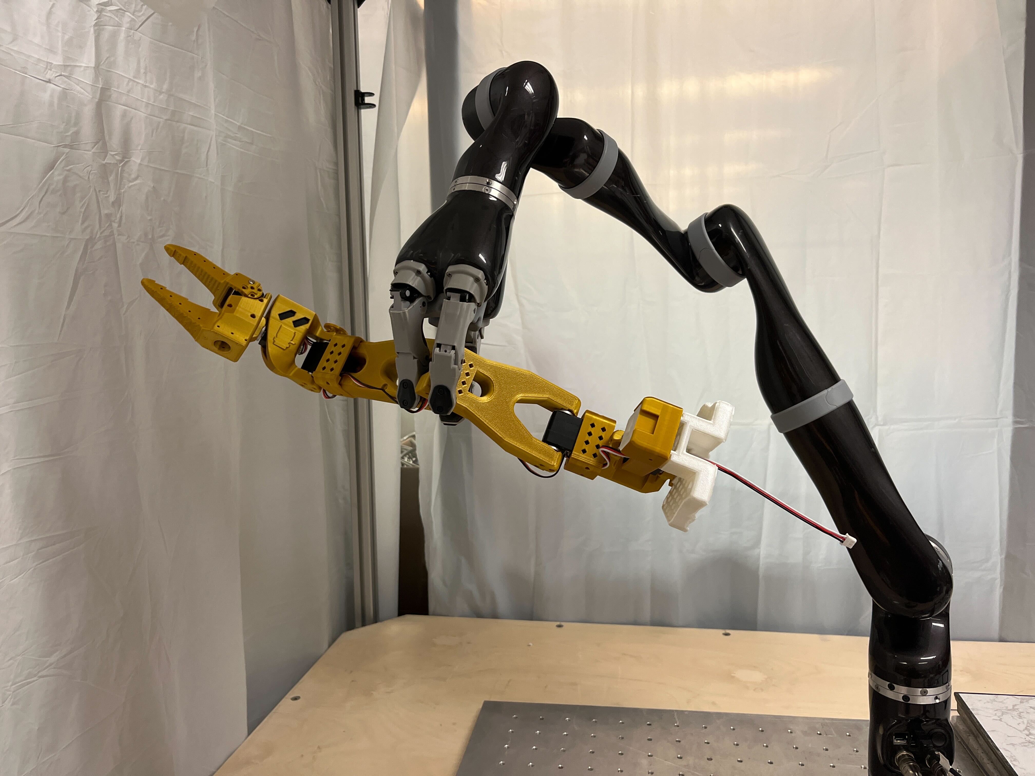
Step 7: Testing and Next Steps
Once the safety “borders” are set up, I could easily control the arm through RViz and project the 3D colored depth on. It works like magic and now the next steps that need to be figured out are how to collect and deploy safely…
Most importantly, I want to keep this environment flexible so I can try new methods of controlling the robot (joint control, end-effector control, torque control—maybe even direct brain interface if I go off the deep end).
Anyway
This setup wasn’t super hard to build, but it does require thoughtful planning. From a cost perspective, you can definitely source cheaper materials if you don’t need industrial-grade extrusions. The main point is:
- Don’t rely on simulation forever. Real-world experiments are where it’s at.
- A solid, safe environment is critical for serious robotics work.
- A kill switch is non-negotiable.
Final setup.
That’s all for now.